Category:One-line diagrams
Jump to navigation
Jump to search
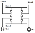
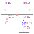
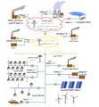
English: In power engineering, a one-line diagram ("single-line" or "executive diagram") is a simplified notation for representing a multi-phase power system. It has its largest application in power flow studies. Instead of representing each of three phases with a separate line or terminal, only one conductor is represented. It is a form of block diagram graphically depicting the paths for power flow between entities of the system.
Deutsch: Ein Einliniendiagramm ist eine Form von Stromlaufplan, welche primär im Bereich der elektrischen Energietechnik Anwendung findet. Wesentliches Merkmal ist, dass die bei einem Stromkreis notwendigen elektrischen Leiter nicht einzeln dargestellt werden, sondern durch eine einzige gemeinsame Verbundlinie schematisch abgebildet werden.
Русский: Однолинейная (чаще всего "исполнительная") схема - один из распространённых видов схем используемых в технической документации электроустановок.
simplified notation for representing a three-phase power system | |||||
| Upload media | |||||
| Subclass of | |||||
|---|---|---|---|---|---|
| |||||
Subcategories
This category has only the following subcategory.
Media in category "One-line diagrams"
The following 143 files are in this category, out of 143 total.
-
110kV substation wiring.JPG 1,270 × 1,300; 92 KB
-
35kV substation.JPG 1,800 × 1,795; 269 KB
-
4-way switching on building plant.JPG 1,100 × 810; 65 KB
-
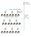
American Distribution System.svg 356 × 415; 59 KB
-
Anwendungsbeispiel EDS.png 300 × 315; 12 KB
-
Anwendungsgebiete von Leistungsschaltern.svg 744 × 1,052; 33 KB
-
Asynchron umformer.svg 350 × 300; 18 KB
-
Barra Anillo.png 324 × 311; 4 KB
-
Barrapartida.png 458 × 250; 3 KB
-
Barrasimple.png 385 × 258; 4 KB
-
Barratransferencia.png 799 × 505; 6 KB
-
Beispiel Werksnetz Lichtbogenofen.svg 634 × 528; 34 KB
-
Bypass.png 385 × 123; 2 KB
-
Cabling layout in old Soviet apartment, built in 1958.JPG 2,736 × 3,648; 3.52 MB
-
Circuit breaker selectivity.JPG 755 × 1,490; 66 KB
-
CS Inverter Topology.jpg 285 × 81; 6 KB
-
CTS.png 264 × 198; 3 KB
-
Current Limiting Reactor.jpg 680 × 361; 21 KB
-
Diff protection.svg 517 × 502; 128 KB
-
Distribution substation wiring.JPG 740 × 1,160; 98 KB
-
Doblebarra.png 799 × 505; 6 KB
-
Działanie dławika przeciwzwarciowego 1 Workaround.svg 359 × 224; 9 KB
-
Działanie dławika przeciwzwarciowego 1.jpg 791 × 480; 97 KB
-
Działanie dławika przeciwzwarciowego 1.svg 337 × 210; 41 KB
-
Electric substation without high voltage switchgear.svg 612 × 584; 20 KB
-
Electrical stove on building plant.JPG 1,100 × 820; 65 KB
-
Electricity grid schema- lang-en.jpg 1,243 × 1,400; 231 KB
-
Electricity Grid Schematic English.svg 1,558 × 2,048; 477 KB
-
Electricity Grid Schematic Hungarian.svg 675 × 906; 698 KB
-
Elektrisüsteemi skeem.png 361 × 389; 36 KB
-
Elmeter high-current.JPG 1,240 × 815; 55 KB
-
Elmeter.jpg 900 × 820; 40 KB
-
Energieverteilung01.png 1,022 × 591; 87 KB
-
European Distribution System.svg 356 × 415; 70 KB
-
Ex-wiring-plan.svg 765 × 990; 92 KB
-
Example of switching diagram.JPG 1,530 × 900; 93 KB
-
Example of TN-C wiki ET.JPG 2,040 × 1,430; 265 KB
-
Example of TN-S.JPG 1,560 × 1,255; 129 KB
-
FACTS shunt compensation1.PNG 511 × 429; 12 KB
-
Grid energy storage.png 1,476 × 886; 85 KB
-
Grid Network.svg 345 × 240; 50 KB
-
Grid storage energy flow.png 935 × 735; 113 KB
-
Grounding knifes.JPG 740 × 560; 22 KB
-
Hvdc bipolar schematic.svg 1,250 × 800; 28 KB
-
HVDC Inga Shaba.GIF 2,919 × 1,536; 77 KB
-
Hvdc monopolar schematic.svg 1,250 × 450; 16 KB
-
HVDC Volgograd Donbass.GIF 2,222 × 1,950; 76 KB
-
Impianto 1 UNIFILARE.jpg 540 × 380; 567 KB
-
Instalacaoeletricapavsupeior.JPG 1,024 × 768; 71 KB
-
Interruptorymedio.png 382 × 355; 4 KB
-
Kolde 100-17 equipotential bonding.JPG 2,240 × 1,440; 254 KB
-
Koormusesobitamise ahel.png 697 × 228; 45 KB
-
LeistSch20.JPG 2,128 × 2,832; 982 KB
-
Light switch diagrams on building plant.JPG 1,080 × 810; 109 KB
-
Line interactive UPS-de.svg 372 × 283; 19 KB
-
Line interactive UPSII.png 462 × 291; 14 KB
-
Line-Interactive UPS Diagram SVG.svg 2,000 × 1,000; 76 KB
-
Line-Interactive UPS Diagram(2).PNG 2,000 × 860; 105 KB
-
Line-Interactive UPS Diagram.png 2,000 × 860; 132 KB
-
Maanduspaigaldis (ET).JPG 1,830 × 1,440; 193 KB
-
Moscow 500kv ring scheme.svg 465 × 390; 43 KB
-
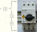
Motor protective circuit breaker with symbol.JPG 570 × 500; 59 KB
-
Multiway switching on circuit diagrams.JPG 2,400 × 400; 63 KB
-
Netzebenen.png 2,013 × 1,894; 288 KB
-
Non sectional system of busbar.svg 216 × 249; 107 KB
-
One-line diagram for dummies.JPG 1,560 × 240; 32 KB
-
One-line diagram of electronic ballast.JPG 980 × 520; 39 KB
-
One-line diagram.svg 450 × 450; 25 KB
-
Overlapping zones of electrical protection.svg 573 × 971; 13 KB
-
Peamaanduslatt (ET).JPG 2,480 × 1,700; 359 KB
-
PowerArabic.png 1,036 × 1,124; 154 KB
-
Prinzip frequenzumrichter.gif 420 × 220; 2 KB
-
Protective relay.jpg 1,087 × 1,450; 1 MB
-
Pulse stab.svg 427 × 267; 15 KB
-
Pulse stab2.svg 427 × 267; 13 KB
-
PxKohliColdIron.jpg 1,322 × 765; 145 KB
-
Quad booster.svg 875 × 563; 23 KB
-
Radial Networks.svg 363 × 254; 52 KB
-
RCD Schaltbild Selektivitaet.PNG 1,080 × 840; 57 KB
-
RCD selectivity between A and B types.JPG 1,140 × 1,320; 95 KB
-
RCD symbols.JPG 560 × 460; 30 KB
-
Refrigerator on building plant.JPG 1,100 × 820; 62 KB
-
Relais nonopt range.JPG 948 × 336; 38 KB
-
Relais opt range.JPG 867 × 336; 33 KB
-
Schem Darstellung Bordnetz.png 1,079 × 646; 103 KB
-
Schema Unifilare Cabina Primaria.png 695 × 722; 13 KB
-
Schematic wiring diagram of electrical stove.JPG 1,900 × 1,200; 184 KB
-
Schuko sockets on building plant.JPG 1,100 × 820; 124 KB
-
Sectional system of busbar with bypass system of busbar.svg 413 × 269; 123 KB
-
Sectional system of busbar.svg 359 × 262; 122 KB
-
Selettività amperometrica.jpg 3,120 × 3,144; 1.37 MB
-
Selettività cronometrica.jpg 2,988 × 2,993; 1.24 MB
-
Signal analyzer block diagram.png 1,315 × 912; 137 KB
-
Single-line wiring diagram of diode bridge.JPG 465 × 220; 15 KB
-
Single-line wiring diagram.JPG 740 × 615; 52 KB
-
SLD skagerrak 3 and 4 png.png 1,284 × 576; 36 KB
-
SLD skagerrak 3 and 4 sens 1 png.png 1,002 × 576; 40 KB
-
SLD skagerrak 3 and 4 sens 1.svg 1,002 × 575; 31 KB
-
SLD skagerrak 3 and 4 sens 2 png.png 1,002 × 576; 41 KB
-
SLD skagerrak 3 and 4 sens 2.svg 1,002 × 575; 31 KB
-
SLD skagerrak 3 and 4 sens 3 png.png 1,002 × 576; 39 KB
-
SLD skagerrak 3 and 4 sens 3.svg 1,002 × 575; 31 KB
-
SLD skagerrak 3 and 4.svg 1,283 × 575; 28 KB
-
SLD yunnan guangdong.svg 2,182 × 1,549; 164 KB
-
Spot Network.svg 345 × 240; 53 KB
-
Standby UPS Diagram SVG.svg 1,000 × 1,000; 21 KB
-
Standby UPS Diagram.png 994 × 586; 34 KB
-
Static VAR Compensator 2a.png 885 × 764; 42 KB
-
Stromversorgung 20240723.svg 1,922 × 1,801; 1.48 MB
-
Stromversorgung.png 1,243 × 1,255; 237 KB
-
Stromversorgung.svg 1,802 × 1,688; 1.48 MB
-
Symbol Neutral-Conductor.svg 43 × 25; 3 KB
-
Symbol of thermal relay.JPG 345 × 230; 18 KB
-
Symbol Protection-Earth-Conductor (alternative).svg 46 × 21; 3 KB
-
Symbol Protection-Earth-Conductor.svg 43 × 21; 2 KB
-
Symbol Protection-Earth-Neutral-Conductor.svg 43 × 21; 3 KB
-
Time-graded co-ordination.svg 600 × 219; 4 KB
-
TLF-2.PNG 530 × 550; 14 KB
-
TLF-3.PNG 530 × 550; 14 KB
-
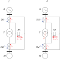
TTR Sec Fault.GIF 640 × 563; 5 KB
-
Umspannwerk Wienerberg 42.JPG 5,184 × 3,456; 4.78 MB
-
Unifilar-cademia.png 960 × 768; 40 KB
-
UPS VFD - Offline UPS (German).svg 750 × 497; 24 KB
-
UPS with double current conversion-de.svg 531 × 283; 22 KB
-
UPS with double current conversion-ru.svg 531 × 283; 23 KB
-
USV passiv.svg 532 × 319; 18 KB
-
Variable-frequency Drive System.png 883 × 462; 36 KB
-
VFD System fr.svg 911 × 456; 23 KB
-
VFD System svg.svg 867 × 477; 23 KB
-
VFI UPS - Online UPS (German).svg 784 × 418; 21 KB
-
VFI-USV.png 896 × 428; 36 KB
-
Vfi.jpg 896 × 428; 67 KB
-
VI UPS - Line Interactive UPS (German).svg 749 × 494; 21 KB
-
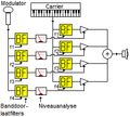
Vocoder.PNG 245 × 220; 6 KB
-
VSI Topology.jpg 285 × 81; 6 KB
-
WikiGif1.gif 522 × 480; 30 KB
-
WikiIPSA.png 1,444 × 1,361; 53 KB
-
Wiring diagram of 3-phase transfer switch.JPG 2,380 × 1,960; 279 KB
-
Wiring diagram of electric cables.JPG 700 × 720; 32 KB
-
Wiring diagram of junction box.JPG 700 × 360; 18 KB
-
Схема электрических соединеий ПС Шестакова.JPG 1,187 × 840; 118 KB






_for_designing_electrical_installations.JPG/120px-Explanation_about_short-circuit_(with_example)_for_designing_electrical_installations.JPG)




.PNG/120px-Line-Interactive_UPS_Diagram(2).PNG)

.JPG/120px-Maanduspaigaldis_(ET).JPG)




.JPG/120px-Peamaanduslatt_(ET).JPG)




.svg/120px-Symbol_Conductors_(three_common%2C_one_neutral%2C_one_protection-earth).svg.png)


.svg/120px-Symbol_Protection-Earth-Conductor_(alternative).svg.png)





.svg/120px-UPS_VFD_-_Offline_UPS_(German).svg.png)


.svg/120px-VFI_UPS_-_Online_UPS_(German).svg.png)


.svg/120px-VI_UPS_-_Line_Interactive_UPS_(German).svg.png)
