Category:Block diagrams
Jump to navigation
Jump to search
- (en) Block diagram
- (ca) Diagrama de blocs
- (de) Blockschaltbild
- (es) Diagrama de bloques
- (fa) نمودار بلوکی
- (fi) Lohkokaavio
- (fr) Schéma fonctionnel
- (hi) ब्लॉक आरेख
- (it) Diagramma a blocchi
- (ja) ブロック図
- (ko) 블록 다이어그램
- (lt) Funkcinė schema
- (nl) Blokdiagram
- (pt) Diagrama de bloco
- (ru) Структурная схема
- (uk) Структурна схема
diagram of a system in which the principal parts or functions are represented by blocks connected by lines that show the relationships of the blocks | |||||
| Upload media | |||||
| Subclass of | |||||
|---|---|---|---|---|---|
| Different from | |||||
| Said to be the same as | Q12535741 | ||||
| |||||
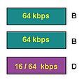
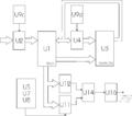
A block diagram is a diagram, in which the principal parts or functions are represented by blocks connected by lines, that show the relationships of the blocks.
Not to confuse with: Category:Block diagrams (cartography)
Subcategories
This category has the following 12 subcategories, out of 12 total.
C
- Control theory block diagrams (293 F)
E
- Entity-relationship models (95 F)
F
- FAST diagrams (7 F)
- Function block diagrams (13 F)
I
J
O
R
V
Media in category "Block diagrams"
The following 198 files are in this category, out of 398 total.
(previous page) (next page)-
Kron spq.png 1,104 × 766; 152 KB
-
Labeled diagram of a self-synchronized synchronous motor-ru.svg 680 × 351; 2 KB
-
Labeled diagram of a self-synchronized synchronous motor.jpg 551 × 282; 29 KB
-
Learning Targets.jpg 1,098 × 384; 61 KB
-
Legacy BIOS boot process fixed.png 6,367 × 1,508; 1.63 MB
-
Legacy BIOS boot process.png 6,367 × 1,508; 1.63 MB
-
Leistungsfaktorkorrekturfilter-Blockschaltbild.svg 550 × 350; 31 KB
-
Libs dia.png 277 × 232; 9 KB
-
Linear growth schematic.PNG 667 × 447; 11 KB
-
Linear tanget.svg 400 × 250; 21 KB
-
Linearisierung multiply.svg 450 × 150; 15 KB
-
LingGr2007.jpg 398 × 366; 136 KB
-
LTDatasetRelation.jpg 474 × 267; 22 KB
-
Ludwig Feuerbachs Projektionstheorie.png 800 × 600; 52 KB
-
Lvit01 electronics block diagram.jpg 2,100 × 838; 149 KB
-
Magnets Diagram.PNG 614 × 371; 11 KB
-
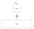
Mass-spring-damper-bond-graph.png 211 × 341; 10 KB
-
Microgrid with RES BESS GRIDconnected.png 560 × 392; 60 KB
-
Milkproducts.svg 1,240 × 780; 86 KB
-
Modeling and Simulation Advantages.jpg 750 × 500; 64 KB
-
Modello2.JPG 378 × 258; 12 KB
-
Modello3.JPG 382 × 161; 4 KB
-
Modello4.JPG 245 × 206; 5 KB
-
Modello5.JPG 183 × 136; 4 KB
-
Modello6.JPG 630 × 146; 8 KB
-
Modello7.JPG 382 × 161; 4 KB
-
Modello8.JPG 571 × 272; 12 KB
-
Modello9.JPG 382 × 161; 5 KB
-
Modelo Porter.png 1,734 × 1,056; 65 KB
-
Modelo Porter.svg 1,734 × 1,083; 183 KB
-
ModPhe1.png 239 × 145; 10 KB
-
Motion control system.jpg 960 × 720; 46 KB
-
Naped elektryczny.svg 1,140 × 300; 33 KB
-
Netfilter-components.svg 710 × 400; 49 KB
-
Niger-Congo speakers.png 2,300 × 4,692; 129 KB
-
Niger-Kongo-Sprachbaum.png 4,423 × 2,504; 144 KB
-
Nigerkongosprecher.png 2,300 × 4,692; 127 KB
-
Noten-Im- und Export.svg 995 × 492; 154 KB
-
NSR1.jpg 553 × 125; 14 KB
-
Ogg vorbis libs and application dia-pt.svg 277 × 232; 27 KB
-
Ogg vorbis libs and application dia.svg 450 × 240; 35 KB
-
OODA.gif 720 × 373; 21 KB
-
OptQersummenzähler.gif 665 × 400; 16 KB
-
Organic growth over time.PNG 704 × 537; 16 KB
-
Outline.JPG 501 × 456; 13 KB
-
PAMP.png 255 × 255; 3 KB
-
Parallel block diagram interconnection (discrete-time).png 380 × 195; 1 KB
-
Parallel block diagram interconnection (in function of s).png 336 × 197; 1 KB
-
Parallel block diagram interconnection.png 401 × 202; 2 KB
-
PARALLELO.png 639 × 626; 5 KB
-
PARAM SET EN.JPG 819 × 507; 36 KB
-
PCM euskaraz.png 368 × 195; 7 KB
-
PDcontrol2.png 1,333 × 652; 14 KB
-
Pds architecture.png 840 × 542; 220 KB
-
Perlwikipedia.png 858 × 259; 94 KB
-
Pfaddiagramm.JPG 512 × 278; 24 KB
-
PIcontrol3.png 1,333 × 652; 15 KB
-
PLC Block Diagram.jpg 940 × 624; 51 KB
-
Podcast-Schema-fr.svg 625 × 263; 16 KB
-
Podcast-Schema.svg 625 × 263; 14 KB
-
Polkit-1-diagrams.svg 559 × 481; 13 KB
-
Prescaler counter.png 3,049 × 853; 86 KB
-
Prinzip Fernwirken.jpg 620 × 247; 14 KB
-
Prinzipielle Darstellung der PCI-Architektur.svg 512 × 362; 79 KB
-
Programming paradigms.svg 2,868 × 2,491; 92 KB
-
Psk transmitter diagram.png 2,001 × 590; 30 KB
-
PSK transmitter.svg 975 × 318; 52 KB
-
QP block diagram.jpg 1,000 × 421; 71 KB
-
Quapason electrical block diagrams.JPG 919 × 288; 38 KB
-
Quersummenzähler.gif 665 × 400; 21 KB
-
Radar Data Acquisition and Transfer Subsystem.png 1,145 × 704; 448 KB
-
Radioprijmač.jpg 814 × 299; 14 KB
-
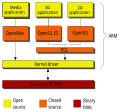
Raspberrypi video API 03.svg 707 × 659; 23 KB
-
Rc hochpass block.svg 512 × 211; 4 KB
-
Rc tiefpass block.svg 512 × 196; 4 KB
-
Reasoned Action Model.jpg 480 × 337; 31 KB
-
Reasoned Action Model.png 960 × 720; 6 KB
-
Rectenna 2.PNG 615 × 113; 5 KB
-
Reliability Block Diagram.JPG 960 × 442; 29 KB
-
Retinoblastoma1.svg 744 × 624; 11 KB
-
RF Enerji Hasatlama Devresi.png 743 × 133; 10 KB
-
RF-fokozat-blokk.png 500 × 162; 9 KB
-
Roman Jacobson theory ar.svg 400 × 250; 64 KB
-
RTOSVisor.png 781 × 360; 64 KB
-
Satellite.png 1,333 × 652; 13 KB
-
Schema a blocchi sistema di campionamento.png 1,005 × 256; 4 KB
-
Schema blocchi modulatore numerico.svg 560 × 326; 7 KB
-
Schema uart.png 701 × 481; 21 KB
-
Schemat blokowy fonogram demonstracyjny..jpg 794 × 1,123; 231 KB
-
Schemat podłączenia bramki VoIP (router z bramką).svg 562 × 205; 6 KB
-
Schemat podłączenia bramki VoIP (router+bramka).svg 571 × 338; 9 KB
-
Schemat podłączenia bramki VoIP (VoIP+PSTN).svg 571 × 338; 8 KB
-
Schematblokowyprojekcji.jpg 1,153 × 640; 62 KB
-
Schéma générique d'un asservissement - II.JPG 827 × 237; 23 KB
-
Schéma générique d'un asservissement.JPG 635 × 239; 21 KB
-
Schéma inondation.png 715 × 353; 30 KB
-
Schéma LIDAR.png 807 × 373; 68 KB
-
Schéma sécheresse.png 743 × 444; 39 KB
-
Series block diagram interconnection (discrete-time).png 407 × 92; 1 KB
-
Series block diagram interconnection (in function of s).png 362 × 97; 1 KB
-
Series block diagram interconnection.png 476 × 106; 1 KB
-
Shamaye sudo code.png 556 × 475; 40 KB
-
Ship's Diesel Engine BrockDiagram NT.PNG 1,080 × 1,200; 142 KB
-
Signalfluss parallel.png 365 × 115; 7 KB
-
Simple Cpu Organization.svg 444 × 113; 65 KB
-
Simple-linear-mech-bond-graph-1.png 364 × 434; 4 KB
-
Simple-linear-mech-bond-graph-2.png 548 × 284; 3 KB
-
Simple-linear-mech-bond-graph-3.png 547 × 259; 3 KB
-
Simple-linear-mech-corrected.png 607 × 509; 6 KB
-
Simple-RC-Circuit-bond-graph-1.png 364 × 295; 3 KB
-
Simple-RC-Circuit-bond-graph-2.png 361 × 221; 2 KB
-
Simple-RC-Circuit-bond-graph-3.png 426 × 271; 3 KB
-
Simple-RC-Circuit-bond-graph-4.png 563 × 377; 5 KB
-
SimpleDmxUniverse.gif 1,540 × 360; 16 KB
-
Sintesi Digital Directa.jpg 594 × 241; 11 KB
-
Sintesi Directa.jpg 504 × 87; 7 KB
-
Sistema misto serie parallelo.png 200 × 97; 1 KB
-
Sitasabre2.jpg 1,085 × 241; 30 KB
-
Sls fcs simple.jpg 639 × 290; 41 KB
-
SMPS Block Diagram.png 600 × 200; 11 KB
-
SMPS Block Diagram.svg 600 × 200; 2 KB
-
Soda Recovery plant.JPG 967 × 561; 54 KB
-
Software-Development-SysML-Block-Definition-Diagram.png 1,294 × 889; 86 KB
-
Software-Development-SYSML-Design-Elements-Block-Definition-Diagram.png 1,180 × 888; 150 KB
-
Something Like Relationship Tree.png 3,158 × 2,670; 4.51 MB
-
SPOD.jpg 743 × 128; 12 KB
-
Srr047h21.jpg 696 × 446; 29 KB
-
START.svg 1,203 × 2,051; 112 KB
-
State-equation-bond-graph-1.png 1,028 × 538; 9 KB
-
Structure.png 400 × 300; 19 KB
-
Summer block diagram fundamental block.png 238 × 209; 890 bytes
-
Superhet.jpg 1,223 × 512; 49 KB
-
Superhet1 pl.svg 1,759 × 779; 51 KB
-
Superhet2.svg 497 × 179; 3 KB
-
Superhetero.jpg 497 × 197; 22 KB
-
Superposition block diagram in electrical components.png 2,421 × 1,437; 54 KB
-
Symbol Shuttle valve with numbers.svg 2,400 × 1,500; 18 KB
-
Symbol Shuttle valve.svg 128 × 67; 7 KB
-
System block diagram 3.jpg 865 × 644; 48 KB
-
Szuperheterodin-ado-FM.svg 1,123 × 794; 26 KB
-
Szuperheterodin-ado-SDR.png 1,800 × 1,403; 120 KB
-
Szuperheterodin-ado.png 1,800 × 869; 88 KB
-
Szuperheterodin-SDR.png 1,630 × 697; 74 KB
-
Szuperheterodin.png 1,956 × 650; 85 KB
-
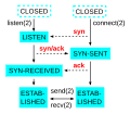
Tcp end.svg 250 × 270; 22 KB
-
Tcp start.svg 230 × 200; 16 KB
-
Technologylazlo2.jpg 513 × 335; 41 KB
-
Telemetry-data flow chart.jpg 1,747 × 1,366; 255 KB
-
Tetrahedron-of-state.png 241 × 311; 10 KB
-
The Wright System Flow Chart.PNG 708 × 1,074; 27 KB
-
Theremin block-diagram.svg 763 × 291; 19 KB
-
Time Series Block.svg 240 × 50; 7 KB
-
TimeCardBlockDiagram.png 2,598 × 1,346; 135 KB
-
Topology CAN protocol.png 669 × 514; 21 KB
-
Total management accounting.png 1,254 × 743; 593 KB
-
Total Solution Process Flow Block Diagram.png 992 × 670; 56 KB
-
Tracking-data flow chart.jpg 1,785 × 1,276; 274 KB
-
Transformer-bond-graph-1.png 1,184 × 371; 11 KB
-
Transformer-bond-graph-2.png 533 × 186; 3 KB
-
Transformer-bond-graph-3.png 583 × 232; 4 KB
-
TriangleTrade CRTExports-1.gif 960 × 720; 18 KB
-
TV-block-diagram.svg 500 × 500; 32 KB
-
Two tone general test.svg 1,287 × 457; 32 KB
-
Two tone Rx test (direct).svg 850 × 397; 29 KB
-
Two tone Rx test (off air).svg 850 × 397; 27 KB
-
Typical Cpu cache organization.svg 695 × 528; 163 KB
-
Typical State Space model with feedback and input.png 446 × 240; 2 KB
-
Uebertragungsglied.png 565 × 344; 6 KB
-
UEFI boot process.png 6,394 × 1,380; 552 KB
-
UF.GridV4.diagrams.png 992 × 802; 57 KB
-
Verbelen Gedragsmodel.gif 393 × 286; 4 KB
-
Video processing pipeline - es.svg 1,010 × 351; 77 KB
-
Video.jpg 1,123 × 794; 44 KB
-
Vliv přenosové funkce na kontrast.png 309 × 328; 16 KB
-
Voltmace Database block diagram.png 1,650 × 1,275; 122 KB
-
Von Neumann architecture uk.svg 420 × 400; 12 KB
-
While Loop .gif 1,550 × 1,080; 86 KB
-
Windows 2000 architecture-ru.svg 663 × 850; 57 KB
-
Windows 2000 architecture.png 700 × 902; 9 KB
-
Windows 2000 architecture.svg 663 × 850; 50 KB
-
X-Realtime Stack.jpg 2,114 × 2,292; 313 KB
-
XDSI-3.jpg 765 × 232; 61 KB
-
XDSI-BRI.jpg 188 × 183; 43 KB
-
XDSI-PRI.jpg 308 × 183; 44 KB
-
XDSI.JPG 761 × 239; 18 KB
-
ZapuC.png 1,631 × 1,444; 15 KB
-
Zwischenkreis-block.svg 625 × 125; 6 KB
-
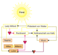
Kabale&Liebe Personenkonstellation.png 800 × 756; 91 KB
-
Блок схема МТ.png 716 × 426; 44 KB
-
Блок схема Эталон.jpg 597 × 201; 14 KB
-
БлоксхемаЭталон1.jpg 1,309 × 479; 32 KB
-
ОШС ОРБ ВС РК.JPG 3,555 × 2,675; 3.83 MB
-
Схема 9.png 879 × 363; 16 KB
-
Схема преобразования сообщений в системе связи.png 1,288 × 156; 13 KB
-
Схема1.jpg 1,575 × 787; 63 KB
-
Функціональна схема фазового вимірювача кутових координат..png 598 × 238; 11 KB
-
نظام الكتروني تقليدي قبل استخدام تقنية i2c.png 657 × 267; 11 KB


.png/120px-Parallel_block_diagram_interconnection_(discrete-time).png)
.png/120px-Parallel_block_diagram_interconnection_(in_function_of_s).png)




.svg/120px-Schemat_podłączenia_bramki_VoIP_(router+bramka).svg.png)
.svg/120px-Schemat_podłączenia_bramki_VoIP_(VoIP+PSTN).svg.png)






.svg/120px-Two_tone_Rx_test_(direct).svg.png)
.svg/120px-Two_tone_Rx_test_(off_air).svg.png)


